

Serial Control
What is Serial Control
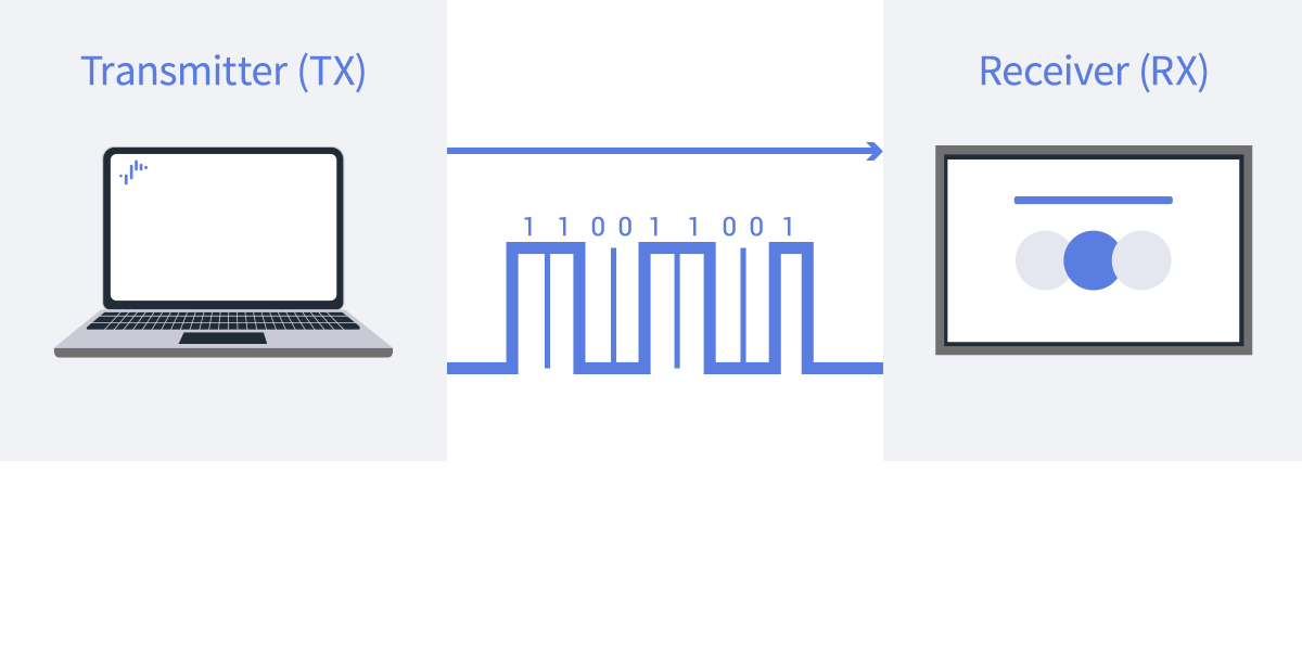
Models with Pro mode support display control and status monitoring from external devices through a serial connection using a 3.5 mm stereo mini jack. The serial communication protocol is designed to communicate with external host devices over RS-232C.
Features
Compact Terminal Design
It is equipped with terminals suitable for space-saving installations where wiring is less affected by the installation environment conditions, such as wall-mounted or narrow spaces.
Stable Communication and Security
It uses a network-independent, one-to-one communication method that is ideal for long continuous operations and sites requiring reliable control.
Compatibility with External Devices
Because it uses a general-purpose protocol, it is designed to easily integrate with AV controllers and control tools, supporting integration with various systems.
RS232C connector and pin assignments
BRAVIA Professional Displays has a 3.5 mm stereo mini terminal for RS232C serial communication. Use a serial cable or adapter that meets the following specifications.
Image preview

Required monitor settings
For RS232C Serial Communication
Required settings for RS232C serial communication.
Procedure: [Settings] →[Remotes & Accessories]→[RS232C control]→Enable [via serial port].
Switch to “Normal Mode” or “Pro Mode” Environment
Set up in Normal mode or Pro mode.
Serial communication protocol
Communication parameter
Before using serial communication, make sure that the serial port settings on the PC or controller match the communication parameter listed below.
If the settings do not match, commands may not be received correctly.
Communication parameter
| Item | Specification |
|---|---|
| Communication Method | RS-232C |
| Synchronous Method | Asynchronous Communication |
| Bit Rate | 9600bps |
| No. of character | 8bit |
| parity | N/A |
| Start bit | 1bit |
| Stop bit | 1bit |
| Flow control | N/A |
Communication data format
Serial control uses three types of communication: Control (command), Query (status request), and Answer (response).
| Type | Description |
|---|---|
| Control | Changes settings or executes functions on the monitor. |
| Query | Retrieves the current status or setting values of the monitor. |
| Answer | Response returned from the monitor. |
About Function
Function is a value used to identify the target function to be controlled or queried.
Each function, such as Power, Input Select, and Program Select, is assigned a unique Function code.
In Control and Query commands, the Function code specifies the function to be controlled or queried.
For a complete list of Function codes, refer to the Command List page.
Example
Power = 0x00Input Select = 0x02Program Select = 0x0B
Command Byte Sequence
Serial control uses binary command communication over RS-232C. Command values are represented in hexadecimal format (0xXX).
Control
Used to request setting changes or execute functions on the monitor.
| Item | Value | Notes |
|---|---|---|
| Header | 0x8C (Control value) | N/A |
| Category | 0x00 (Fixed) | N/A |
| Function | 0xXX (Target function) | N/A |
| Length | 0xXX (= X + 1 byte) | Total number of bytes from Byte0 to Check Sum (including Check Sum) |
| Byte0 | 0xXX (Setting value) | N/A |
| ByteX | 0xXX (Setting value) | For commands with multiple data bytes |
| Check Sum | 0xXX | Least significant byte of the sum from Header to ByteX |
Example Power Off
0x8C 0x00 0x00 0x02 0x00 0x8E│ │ │ │ │ └ Check Sum│ │ │ │ └── Byte0 (OFF)│ │ │ └───── Length│ │ └──────── Function (Power)│ └─────────── Category (Fixed)└────────────── Header (Control)
Query
Used to retrieve the current status or setting values of the monitor.
| Item | Value | Notes |
|---|---|---|
| Header | 0x83 (Query value) | N/A |
| Category | 0x00 (Fixed) | N/A |
| Function | 0xXX (Target function) | N/A |
| Byte0 | 0xFF (Fixed) | N/A |
| Byte1 | 0xFF (Fixed) | N/A |
| Check Sum | 0xXX | Least significant byte of the sum from Header to Byte1 |
Example Power Query
0x83 0x00 0x00 0xFF 0xFF 0x81│ │ │ │ │ └ Check Sum│ │ │ │ └── Byte1 (Fixed: 0xFF)│ │ │ └───── Byte0 (Fixed: 0xFF)│ │ └──────── Function (Power)│ └─────────── Category (Fixed)└────────────── Header (Query)
Answer
Response returned from the monitor to the PC. The value of Answer varies depending on the response status.
| Answer Status | Value | Description |
|---|---|---|
| Completed | 0x00 | Operation completed successfully. |
| Limit Over (Upper Limit) | 0x01 | The specified value exceeds the upper limit. |
| Limit Over (Lower Limit) | 0x02 | The specified value is below the lower limit. |
| Command Canceled | 0x03 | The request was received but could not be processed. |
| Parse Error | 0x04 | Invalid packet format or Check Sum error. |
Answer Example: Response to a Control Request (Display → PC)
A Control request returns an Answer indicating the execution result.
| Item | Value | Description |
|---|---|---|
| Header | 0x70 | Fixed value “Answer” |
| Answer (Completed) | 0x00 | The packet was received successfully and the operation completed successfully. |
| Answer (Upper Limit) | 0x01 | The packet was received successfully, but the specified value exceeds the upper limit. |
| Answer (Lower Limit) | 0x02 | The packet was received successfully, but the specified value is below the lower limit. |
| Answer (Command Canceled) | 0x03 | The packet was received successfully, but the request could not be processed due to invalid data or the current host status. |
| Answer (Parse Error) | 0x04 | The packet could not be received correctly, an undefined format was received, or a Check Sum error occurred. |
| Check Sum | 0xXX | Least significant byte of the sum from Header to Answer |
Answer Example: Response to a Query Request (Normal Completion)
A Query request returns an Answer and Return Data.
| Item | Value | Description |
|---|---|---|
| Header | 0x70 | Fixed value “Answer” |
| Answer (Completed) | 0x00 | The packet was received successfully and the operation completed successfully. |
| Return Data Size | 0xXX | N+1 bytes. Total number of bytes from Return Data1 to Check Sum. |
| Return Data1 | 0xXX | Returned value. |
| Return Data N | 0xXX | Returned value. |
| Check Sum | 0xXX | Least significant byte of the sum from Header to Return Data N |
Answer Example: Response to a Query Request (Error)
Normally, a Query request returns an Answer and Return Data. If an error occurs, Return Data is not returned.
| Item | Value | Description |
|---|---|---|
| Header | 0x70 | Fixed value “Answer” |
| Answer (Command Canceled) | 0x03 | The request was received but could not be processed in the current state. |
| Answer (Parse Error) | 0x04 | Undefined format data was received or a Check Sum error occurred. |
| Check Sum | 0xXX | Least significant byte of the sum from Header to Answer |
Remarks
For Commands via HDMI
Required settings when commands via HDMI connection.
Procedure: [Settings] → [Remote control & accessories] → [RS232C control settings] → Enable [Via HDMI port].
Note:
To control, you need to prepare a conversion device such as a decoder to convert HDMI signals to RS232C control signals (not recommended).
When using external devices such as STBs, also enable BRAVIA Sync.
Procedure: [Settings]→[Inputs] → [BRAVIA Sync settings]